


1. Product Structure
1.1 Basic structure of aluminium-plastic composite pipe (figure 1)
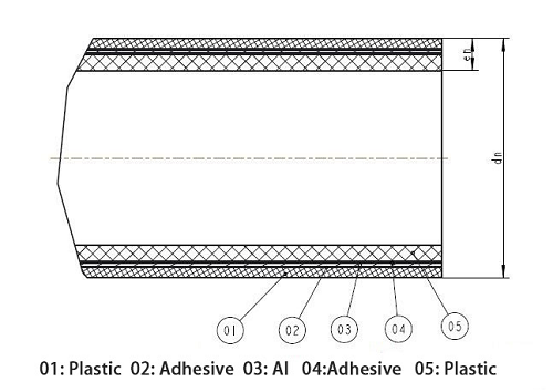
Figure 1: Basic structure of aluminum-plastic composite pipe
1.2 Basic structure of compression fittings (figure 2)
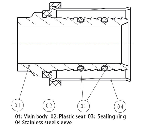
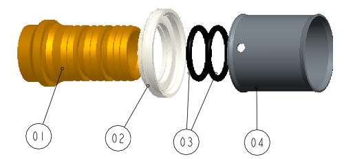
Fig .2: Basic Structure Diagram of Pressure Type Pipe Joint
1.3 Basic types of compression fittings
Type U, TH, Multi-jaw (multifunctional)(Figure 3)
1.4 Matching crimping tools
German REMS brand or other brand tools of the same size as the brand should be used for matching pressing tools (figure 4).
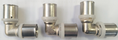
U TH Multi-jaw
Figure 3: Type of Calendering Pipe
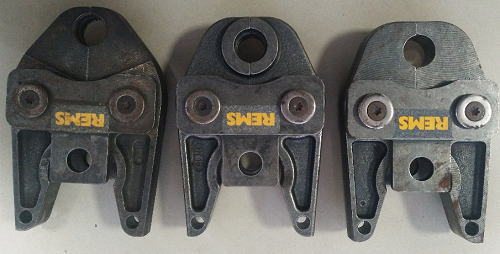
Figure 4: REMS Tool Example
2. technical parameters
Specification: dn 16*en2.0dn20*en2.0dn25*en2.5dn26*en3.0dn32*en3.0
Application conditions: class2-10bar class4-10bar class5-10bar
Installation Location: Indoor Installation
3. working principle (Figure 5)
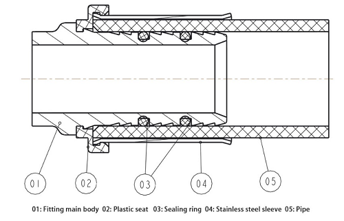
Figure 5: Diagram of pipe and fittings assembly
The sealing ring (03) is tightly bonded with the pipe fittings, and the stainless steel sleeve (04) is deformed by the special pressing tool to press the pipe (05) tightly on the pipe fitting body (01) joint to realize the connection.
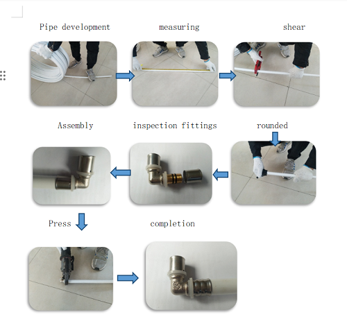
4. clamping connection installation steps
4.1 Preparation of materials and tools
All relevant materials and tools shall be prepared in accordance with the construction design requirements, including pipes, fittings, scissors, round chamfering devices, special pressing tools and other materials required for the construction site.
4.2 Management and Measurement
The required aluminum-plastic composite pipe is expanded (the ring pipe is applicable, the straight pipe is not needed) and the expanded aluminum-plastic composite pipe is measured according to the construction drawings or the actual requirements of the site.
4.3 Cutouts
Cut the measured pipe with special pipe shears.
4.4 Round chamfer
The cut aluminum-plastic composite pipe port is rounded with the whole chamfer, and the inside and outside of the port are chamfered.
4.5 Inspection of fittings
Check that each joint fitting is complete (figure 2) and in place before assembly.
4.6 Assembly
The whole round chamfering pipe is inserted smoothly along the axial direction of the pipe and fittings, and whether the pipe is inserted in place through the observation hole (U type) on the stainless steel sleeve or the observation hole (TH type and M type) on the plastic protective sleeve.
4.6 Press
Open the special pressing tool, select the appropriate type and specification of the pressing clamp block, the side of the U type and the RFz type pressing clamp block is close to the side of the plastic protective sleeve near the stainless steel sleeve, and the plastic protective sleeve is embedded in the positioning groove of the clamp.
4.7 Connection diagram (U example)
Attention 3. construction and maintenance
a. aluminum-plastic composite pipes, fittings and matching pressing tools must use our supporting products or other brand products approved by our company.
b. aluminum-plastic composite pipes and fittings should be stored indoors to avoid rain and direct sunlight.
c. aluminum-plastic composite pipe should be strictly local construction standards.
d. During construction, pay attention to light and light, do not bump each other, do not rub with hard objects, so as not to cause pipe and fittings deformation, damage.
e. the pipe should be placed on a soft surface or a flat hard surface, the pressure of the pipe should be moderate, to avoid damage to the surface of the pipe due to hard objects, due to excessive deformation according to the pressure.
f. shearing end should be perpendicular to the axis of the pipe, no visible tilt, burr, etc . (figure 6) 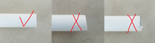
Figure 6: Schematic diagram of whether the pipe is cut correctly or not
g. Before connecting pipe and fittings, the pipe must be rounded to avoid difficult insertion, sealing ring movement, sealing ring breakage and so on (Fig .7).
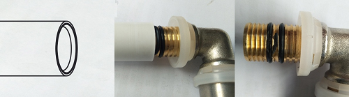
Figure 7:Schematic diagram of chamfering and problems caused by not chamfering
h. Pipe and fittings must be inserted evenly along the axial direction to avoid excessive force leading to seal displacement or damage (figure 7), intubation must be in place, The insertion can be observed through observation holes (U) on stainless steel sleeves or observation holes (TH and Multi-jaw) on plastic protective sleeves (figure 8).
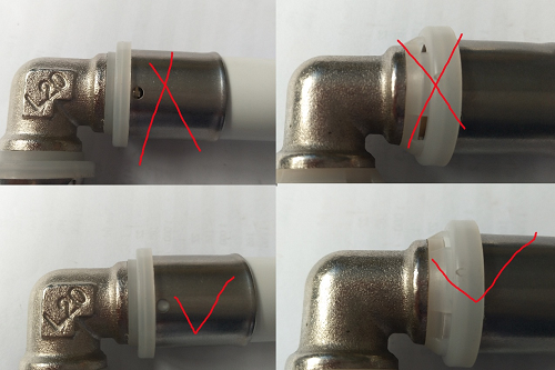
U type TH and Multi-jaw
Figure 8: Schematic diagram of intubation in place
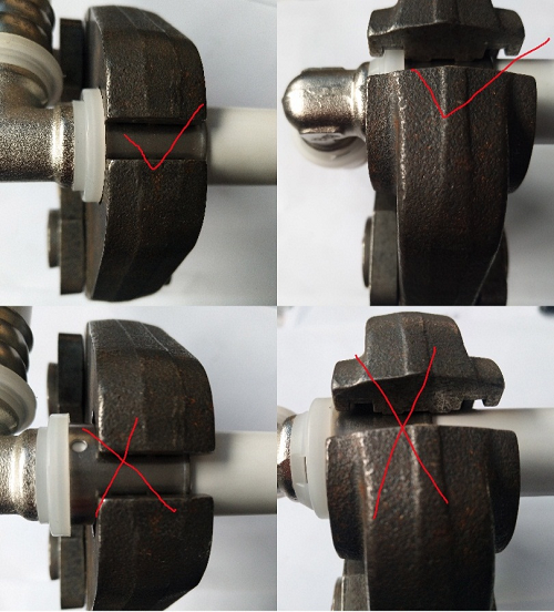
U or RFz TH
Figure 9: Diagram of crimping location
i.The end face of the clamp block must be close to the end face of the plastic protective sleeve (U type and RFz type) or embedded in the fixture positioning slot (TH type)(Fig .9). Otherwise, it may lead to pipe removal or leakage.
Hubei Gangan Fluid Technology Co., Ltd.